If you purchase products by clicking those links, I may earn an affiliate commission.
Update: since writing this, I’ve replaced the entire Raspberry Pi setup described in this post with a MiSTer FPGA and a MiSTercade from MiSTer Addons. Everything was easier to configure, runs much better, and I’m far happier with this setup than I was with trying to make a Raspberry Pi do what I want in an arcade cabinet.
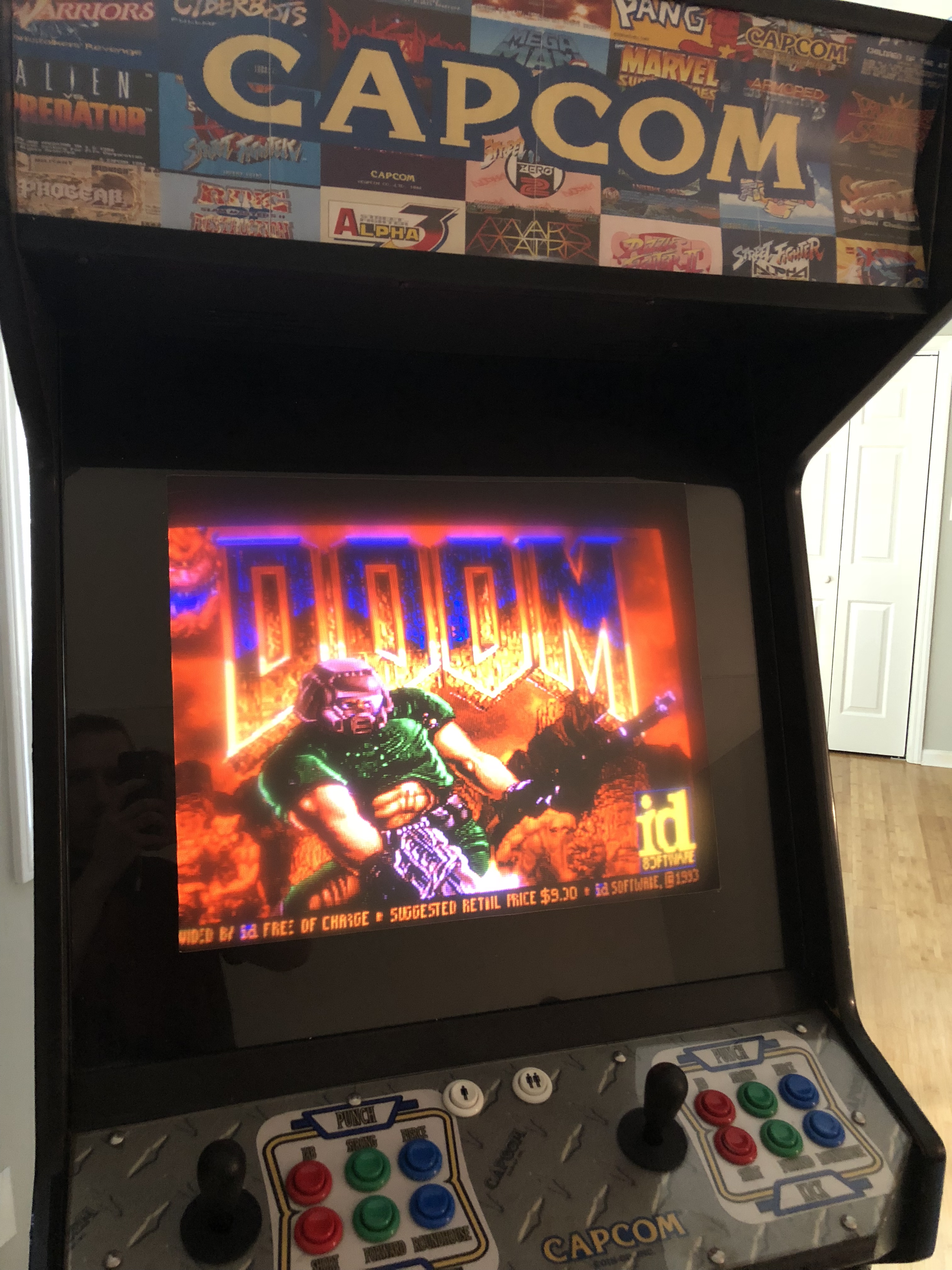
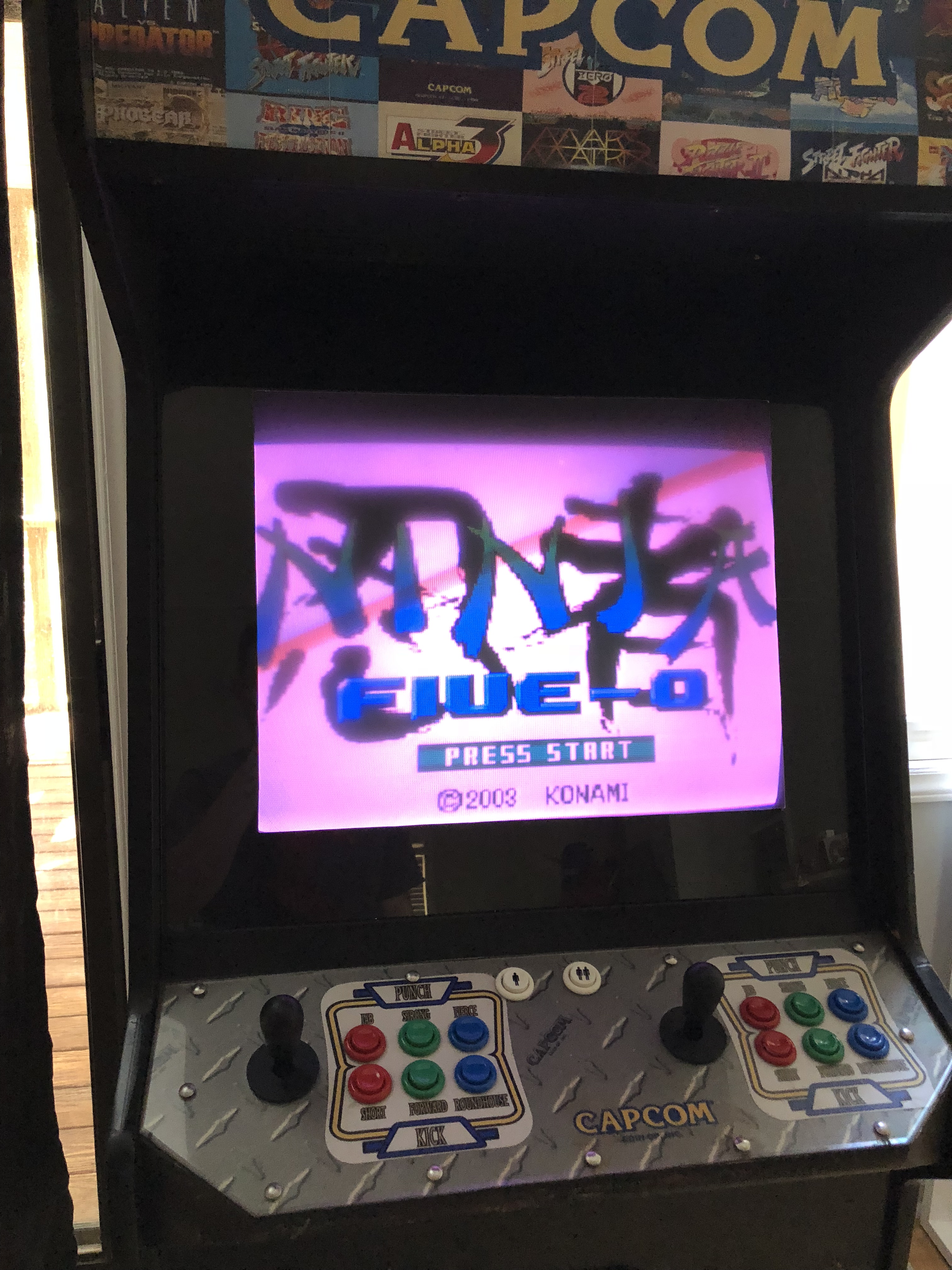
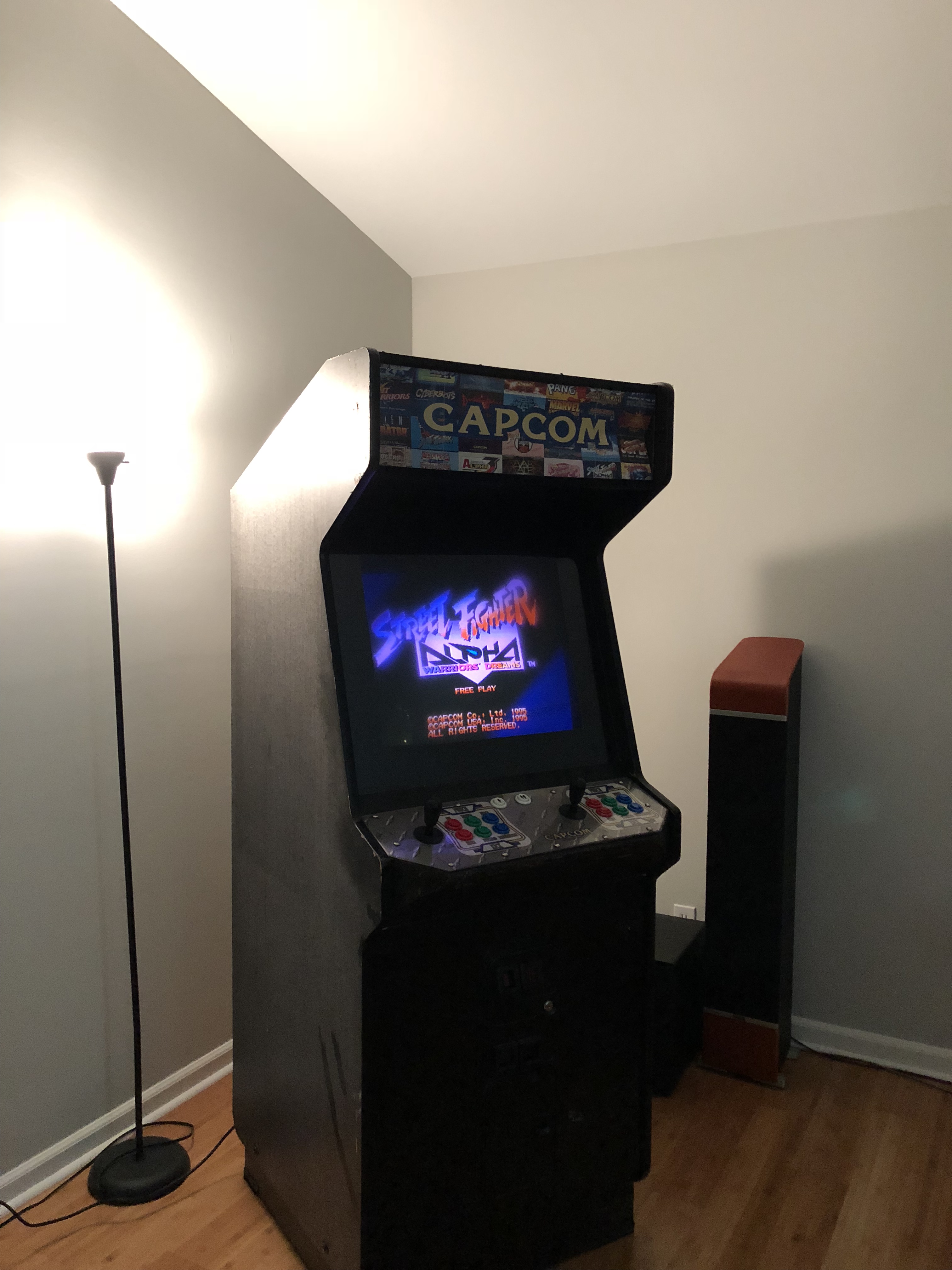
We recently acquired (for free!) an original Street Fighter Alpha: Warriors’ Dreams arcade cabinet that we wanted to be able to easily play other games on. A Raspberry Pi seemed like a good way to experiment with this in the initial stages, as there are already a large number of distributions for it which boot straight into an emulator frontend (such as Lakka, RetroPie, and Recalbox), and I figured there would be some documentation available on the web from other people who had done arcade cabinet conversions with a Raspberry Pi.
This post is intended as a summary of what I learned in the process, and a rough guide for anyone who wants to do something similar and isn’t super-familiar with arcade electronics.
I’ve also made a convenient Amazon Shopping List of the parts I’ve used available here.
Connecting a Raspberry Pi to JAMMA
Since arcade operators often wanted to use the same cabinet for different games, a standard connector (the JAMMA connector) was adopted to make changing games easier. This handles input buttons, power, and video signals. Since I wanted to have the ability to switch back to original arcade hardware (and not have to constantly rewire everything), I wanted to also use the standard JAMMA connector to connect my Raspberry Pi.
There are a number of boards that attach to the Raspberry Pi’s GPIO pins and connect directly to JAMMA:
The issue I had with these is that many seemed to be poorly documented and have mixed reviews. I didn’t want to be locked into whatever emulator/OS/frontend happened to work with a particular board, with no documentation available for using something else. I also didn’t want to spend $150 on a board/adapter that would only work with a Raspberry Pi - I wanted something more generic that would give me an upgrade path (to a full x86 PC, for example) later on.
The Ultimarc J-PAC ($59) seemed to be the best solution for this. It converts the JAMMA connector to standard VGA and USB (converting the arcade buttons to act as a keyboard), making it easy to connect to a Raspberry Pi or other computer.
Video
The J-PAC takes VGA input and sends it to the JAMMA connector, so that you can use your existing arcade monitor wired onto the JAMMA harness. That leaves you with the question of how you want to get arcade-monitor-compatible VGA from the Raspberry Pi. A lot of people say they use an HDMI-to-VGA adapter, with a GBS-8100 converter board to convert the signal to be 15KHz arcade-compatible. My personal experience tells me that every video conversion step introduces latency, and since this is an arcade cabinet, I wanted as little latency as possible.
Luckily, it’s not only possible to use the Raspberry Pi GPIO pins to get a VGA signal, you can also drive an arcade monitor directly from it. The adapter is the open-source Gert VGA666 adapter, which is available pre-assembled here (make sure you read the fine print if you order from somewhere else, as most are sold un-assembled and will require soldering). The only other real catch is that the J-PAC for some reason has a male VGA connector, and all the VGA cables I had sitting around were male/male, so I needed a VGA gender changer in order to connect the J-PAC and VGA666 (you can cram the VGA666 directly into the J-PAC, but it’s pretty hard with the USB micro cable right next to it, so I probably wouldn’t recommend that as a long-term solution).
With the VGA666 you do need some extra configuration for 15KHz VGA output in your boot partition’s config.txt. The specific modeline and timings you need to use may vary according to your monitor’s settings, but you can start with the settings from this page, e.g.:
dtoverlay=vga666
enable_dpi_lcd=1
display_default_lcd=1
dpi_group=2
dpi_mode=87
hdmi_timings=320 1 20 29 35 224 1 10 14 16 0 0 0 60 0 6400000 1 # 320:224
Or for something closer to my original CPS2 resolution/timings:
hdmi_timings=384 1 0 11 28 224 1 10 0 30 0 0 0 60 0 6400000 1 # 384:224
There’s many more sample modelines and additional information available here: http://sommerp.net/doku.php?id=raspberry_pi_arcade (dead link, archived version here)
If you upgrade to a full x86 PC, GroovyMAME/GroovyArcade seems like a good option specifically designed for running on original arcade monitors.
Sound
This, for me, was one of the most confusing and poorly-documented parts of converting an existing arcade cabinet. Since the J-PAC needs amplified audio to pass through to the JAMMA connector, you’re kind of left out on your own. Most of the posts I could find were “well, I ripped the amplifier out of a random amplified speaker I had sitting around and figured it out for myself,” or, “I replaced the arcade speaker with some cheap amplified PC speakers,” which weren’t very helpful to me.
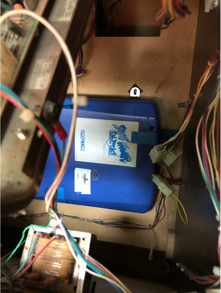
First, some background on what the typical arcade cabinet speaker even is and what might be in your cabinet. If your speaker is driven through the standard JAMMA connector, it will be a single mono speaker, probably located in the top of the cabinet. Everything I’ve found indicates that these are usually cheap, small, 4-8 watt, 8 ohm speakers, which I assume is accurate. There’s a special caveat for CPS2 cabinets here though, which is that if your CPS2 board has standard red/white RCA cables connected to it next to the kick harness, you’re probably in luck and already have amped stereo speakers in-cabinet driven off the arcade power supply. If this is the case, all you’ll need to drive your sound directly off the Raspberry Pi (no need to go through the J-PAC!) is a standard 3.5mm to RCA adapter.
If you have a standard mono speaker, welcome to Options Town, population: you. Of course, you can take the aforementioned route of converting your cabinet to a standard amped speaker and bypassing the J-PAC. I didn’t really want to do this as I wanted to keep everything as original as possible, with the option of easily swapping back to original arcade hardware or plugging in a completely different JAMMA arcade board (even a non-CPS2 board with standard JAMMA audio). I also wanted as few power supplies hooked up as possible, and driving an amplified speaker off an arcade power supply could be tricky.
If you’re keeping the original mono speaker, what you want is a small mono amp between the Raspberry Pi and the J-PAC. Searching for these can be a little bewildering, so here’s what I’ve turned up:
- SMAKN LM386 (or Icstation LM386 or Gikfun LM386)- 5V-12V, 0.5-10W, mono
- Adafruit PAM8302 (or HiLetgo PAM8302) - 5V, 2.5W, mono
- TPA3118 (alternate version) - 8-24V, 60W, mono
- Icstation PM2038 (or Walfront PM2038 or Daier PM2038) - 5V, 5W, stereo, has USB/3.5mm connections
There are probably more you can find, or far more stereo amplifiers you could just use one channel off of. The complicating factor is really getting power to the amplifier. If you’re fine with running another power supply into your cabinet, you can go hog wild, but if you want to use the Raspberry Pi your options are 5V or nothing. If you’re a little more adventurous, you can probably pull 5V or 12V from the arcade power supply (there are some instructions here for modifying your J-PAC to reassign 5V or 12V power out from one of the JAMMA pins). An LM386-based amp would give you the option to run on 5V from the Raspberry Pi and later switch to 12V if you want to or need more power, if you wanted to go that route.
Another complicating factor is how comfortable you are with wiring things up in order to be able to connect everything. Most of these amps have simple through-holes or screw terminals for everything, so you’ll either need to sacrifice an existing cable, buy a true breakout cable, or buy a breakout adapter in order to connect the power and audio. If you’re using the Raspberry Pi for power, the idea is to pull 5V from USB, so you can use the ground and 5V from a USB Micro-B or USB Mini-B breakout board to do this easily. You can use a 3.5mm breakout board for the audio. You can also get a pack of solderless-connector wires to make everything easy. You can then pull together your breakouts and amp board on a mini breadboard. Be warned that without fixing the components or connections together in some way, keeping everything together when you’re jamming it into your cabinet may be pretty tricky. Another consideration: your arcade power supply is going to be putting out a lot of interference, so you want your amp as far away from it as possible, and maybe in something like a project box to protect it.
If you’re not comfortable wiring a bunch of things up, just get one of the PM2038-based options listed above. The shipping is a little slower but they already have USB and 3.5mm audio connections wired together, so you can connect it to the Raspberry Pi with just a USB-A cable and 3.5mm aux cable. Then you can just use the screw terminals and jumper wire to wire the amp’s left channel to the J-PAC. This is what I finally wound up using, and is really the route I’d suggest for most people. For me, it’s plenty loud even with the volume set about halfway.
If you’re worried about potentially losing a channel with stereo-audio games and mono audio, this post has some instructions for downmixing to mono with ALSA.
Inputs
If you’re using a RetroArch-based distribution on your Raspberry Pi (like Lakka, RetroPie, or RecalBox), you’ll need to map the inputs for the J-PAC. You can set this in retroarch.cfg (omitting the first four lines), or try to use the following as an autoconfig (by copying to your Lakka SAMBA share’s “Joypads” mount):
Keeping the J-PAC default input code table handy will probably be helpful as well, as there are some combination inputs that won’t be immediately obvious (e.g. 1P start + left for enter, 1P + 2P start for escape). A tricky point for me was the P2 coin insert for MAME - some arcade games will only start player 2 from a P2 coin insert, and while my P1 coin chute worked correctly, my P2 coin chute didn’t. To get around this I changed my RetroArch config to omit “input_pause_toggle = p” and have “input_player2_select = p”. After this, pressing 1P + down worked as a P2 coin insert for MAME.
Another issue is that many of the default retroarch.cfg button mappings overlap in awkward ways with the default J-PAC keyboard codes (so, for example, pressing a button might wind up mapped to both an “A” button press and the emulator fast-forward function, which makes for some strange gameplay). The only solution (as far as I can tell) is to override all those settings with "nul" values. To do this, you can access “Configfiles” off your Lakka SAMBA share, then copy retroarch/retroarch.cfg to a local directory, apply this patch with patch -p1, then copy the patched retroarch.cfg back to your Lakka share (and then restart Lakka/RetroArch). This patch also sets the button configs to those described above, just in case there’s problems loading the Joypads config.
Kick Harness
Standard JAMMA only supports two players and three buttons per player, so if you’re converting a CPS2 cabinet you probably have an extra three buttons per player (if you have a four player cabinet, you’ll also need to do some work to wire the extra buttons/players up, but you’re on your own for that). These are the bottom row “kick” buttons, which are wired on the “kick harness” that connects to the CPS2 board next to the JAMMA connector.
This wiki page on CPS2 kick harnesses was incredibly helpful for hooking this up. With the part numbers linked from there, I ordered the kick harness board end connector (part no. DF1BZ-34DP-2.5DSA) from Digi-Key and wired it up to my J-PAC with male/female solderless cables.
Using the pin-out from the SF Alpha arcade manual was also helpful for getting the correct pin order for my actual haness, which thankfully matched the manual’s color codes:
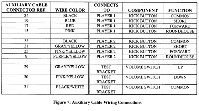
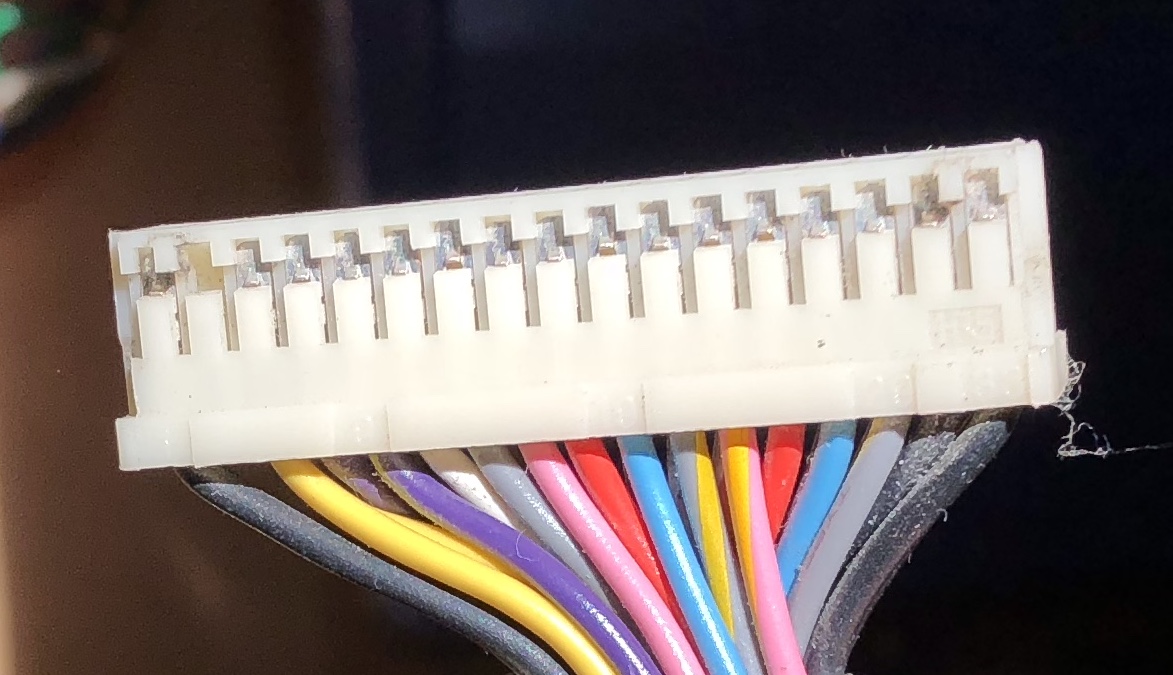
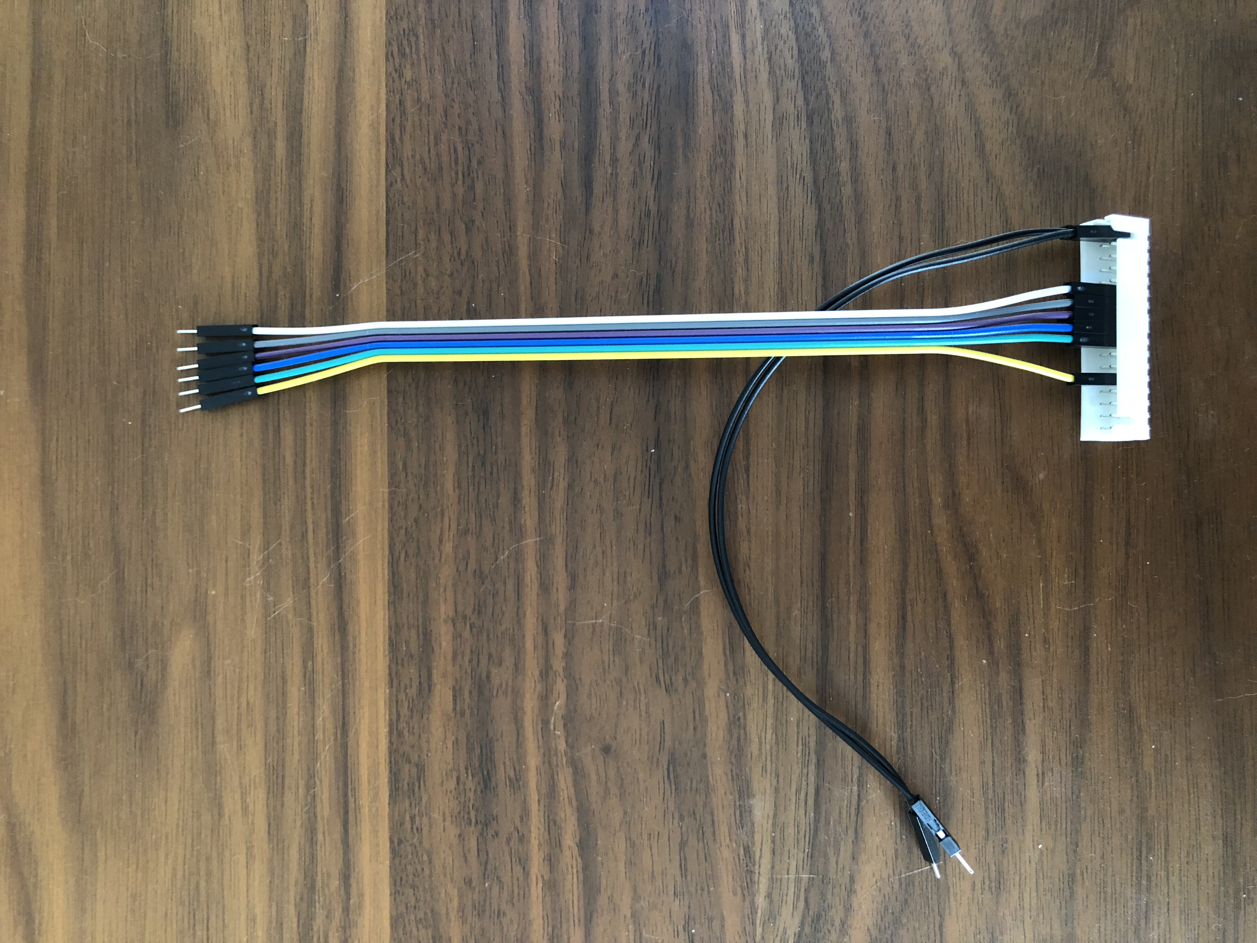
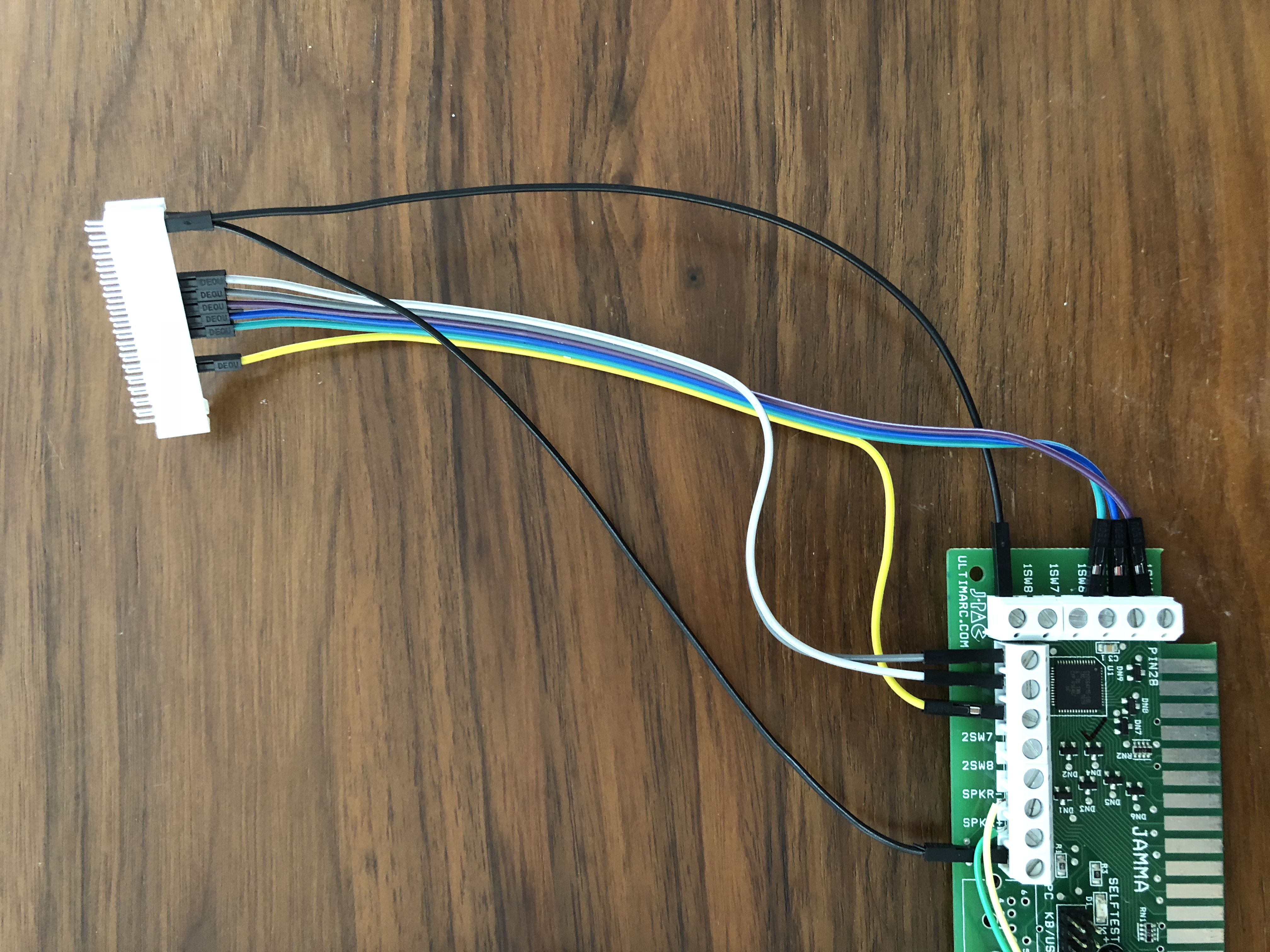
You can see I actually wired the connector up with the solderless cables on the “outer” end of the connector that would normally connect to the arcade harness, since the pins are longer on that side and the cables have a more solid connection that way - plugging the existing arcade harness into the “board” side of the connector works fine.
Conclusion
At the end of all this, you should have a working arcade cabinet that you can use for MAME with a Raspberry Pi or PC, while still being able to easily switch back to original arcade boards. In the future I’d like to try to power the Raspberry Pi off the arcade power supply, but right now I’m happy with working sound and inputs. Hopefully this guide helps someone else who’s as confused as I was!